Electronica: Magnetic angle sensor IC works over 46 turns, with the power off
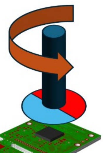
by Steve Bush · Electronics Weekly.comADI has announced an IC that can not only measure the angle of a nearby rotating magnet, but can count up to 46 complete turns even when the chip has no power.
For those who like puzzles, look away for a couple of minutes to work out the mechanism for yourself, as it is going to be explained in the next paragraph.

On the IC, called ADMT4000, is a micro-scale spiral of ferromagnetic wire, arranged so that a magnetic field rotated in the correct plane will propagate magnetic domain walls along the spiral. This happens whether the IC has power or not.
The wire is built from materials which exhibit the ‘giant’ magneto-resistance (GMR) effect, which means that the location of a domain wall can be located, once the chip has power, by sensing resistance between electrodes connected at intervals along the length of the wire.
Read our full Electronica 2024 coverage »
When the chip is powered normally, it also measures the magnet’s instantaneous angle to within ±0.25° through a pair of on-die Wheatstone bridges orientated at 45° to one another.
Theses are constructed from resistors exhibiting the anisotropic magneto-resistive (AMR) effect, allowing these bridges to produce sine and cosine voltages that can be processed into an angle.
However, “the sine output and the cosine output measure one full cycle for every 180° rotation of the external magnetic field”, according to the company, leaving an ambiguity.
This ambiguity is removed by a third internal magnetic sensor, the second GMR sensor, which is arranged to unambiguously indicate which quadrant of a full rotation the magnet is in at any moment – allowing internal processing to extend the AMR’s 0 -180° output to 0 – 360°.
When powered, complete rotations of the ambiguity-corrected AMR angle are counted over a range of -9 to +54 turns, anchored to the 0 to +46 turns (0 – 16.560°) range of the non-volatile GMR spiral.
“The extended range of the AMR angle-sensor-derived-turn-count is to facilitate system calibration only, and should not be used in the normal operation of the part,” said ADI, further warning: “If the external magnetic field is rotated beyond the 0 to 46 turn range of the GMR turn sensor in the power-off state, the reported angle can be incorrect with no fault flag set after the next power-on.”
All of the above are measured by a single 12bit successive approximation (SAR) ADC, with front-end sample-and-holds ensuring that simultaneous AMR bridges readings are taken to reduce phase errors when the magnet is moving.
Factory set calibration coefficients are stored in non-volatile memory to correct readings, and an internal temperature sensor is included to provide further data for external corrections.
Magnetic domains in the GMR spiral can become corrupted, for example if the IC is subjected to a high magnetic field, and it will need re-setting by applying an external field of ≥60mT for ≥10μs at 315°.
An external electromagnet on the PCB can be used to generate this field, or the actuating magnet can be chosen to deliver the reset field when pushed close to the IC, but be positioned far enough away at other times to provide the specified 16 to 31mT operating field.
Development is supported by the EVAL-ADMT4000 board and associated ADMT4000DRV-SRC software package.
“The target audience includes manufacturers of industrial actuators, drives, encoders, robots, cobots and humanoids,” said ADI. Other markets of interest include automotive sensors and actuators, aerospace and defense, medical scanners and dentist chairs.
Find ADMT4000 at Electronica in Munich (hall C4, stand 121, 12 – 15 November), SPS in Nuremberg (hall 5, stand 110, 12 – 14 November) or on the ADMT4000 web page right now.